Lorentz force DC motor
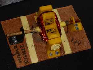
This is a DC motor I built for EIR 221 at the University of Pretoria. We were limited to a R200 budget ($10) and had to build it during a one-week recess.
I got it working in two days, providing me with some spare time during the recess.
Watch a video of the early prototype
Operating principle
Unlike most DC motor projects, which use an alternating electromagnet to push the rotor away from the magnets, this motor uses the Lorentz force, which is the force experienced by a copper wire near a magnet while current flows through the wire.
Because there are 100 windings, this force is multiplied by 100, which gives the rotor enough momentum from standstill to turn 180 degrees, allowing the wire at the opposite end to get near the magnet.
At that point, the Lorentz force would be operating in the opposite direction, slowing the motor down, except that the commutator (the metal on the axle that is touching the paperclips) is flipped around, which flips the direction of the electrical current and therefore the Lorentz force.
Brushes
The brushes are just paperclips that were bent into shape. Their purpose is to provide a stationary electrical connection to the spinning rotor.
At the end of the project, they were held in place with masking tape.
Rotor design
All 3D-printed parts were designed in Autodesk Fusion.
First iteration

The first iteration of the rotor was a failure, as there was only enough room for about 20-30 windings. This was not enough windings to provide enough resistance to the battery, causing the voltage to drop under the massive current draw. In more technical terms, the rotor was poorly impedance-matched with the battery.
The surface that the windings lay on was also flat instead of curved, so the diagonal length of the rotor was longer than its longitudinal length, which meant that the windings would only get close to the magnets in four positions.
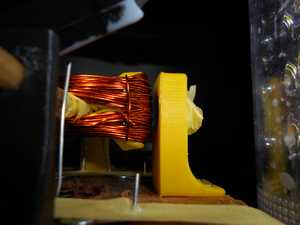
Second iteration

In the second iteration, in order to increase the rotational inertia, material was added to the outside and holes were added for nails, which also served to focus the magnetic fields from the magnets toward the windings (at least in theory).
The windings were also designed to follow a curved contour, keeping them close to the magnets.
More room was added for 100 windings, which still ended up being too few for the lab's bench power supply, but which was enough for fully-charged 9V batteries.
Commutator
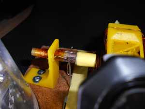
The commutator is just a few sanded-down pieces of magnet wire soldered to the magnet wire coming from the rotor.
Soldering this wire was tricky, as the thick magnet wire conducted most of the heat away from the 48W soldering iron.
Some masking tape and Kapton tape was later added to keep the commutator fixed and prevent the axle from moving laterally.
Speed sensor
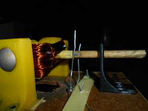
The assignment required an additional commutator to act as a speed sensor. This commutator is made of two nails with some wire wrapped around them to connect them electrically. The brushes (paperclips) are electrically connected twice per revolution, allowing for speed measurement via an oscilloscope.
Video
Here is a an early version of the motor connected to a 9V battery. To get a sense of the speed, turn on the sound.
What should have been done differently
The rotor should have been designed to allow for even more windings with a greater arc length.
More time should have been spent while making the commutator in order to increase the duration of contact made with the brushes.